Hydrogen Storage
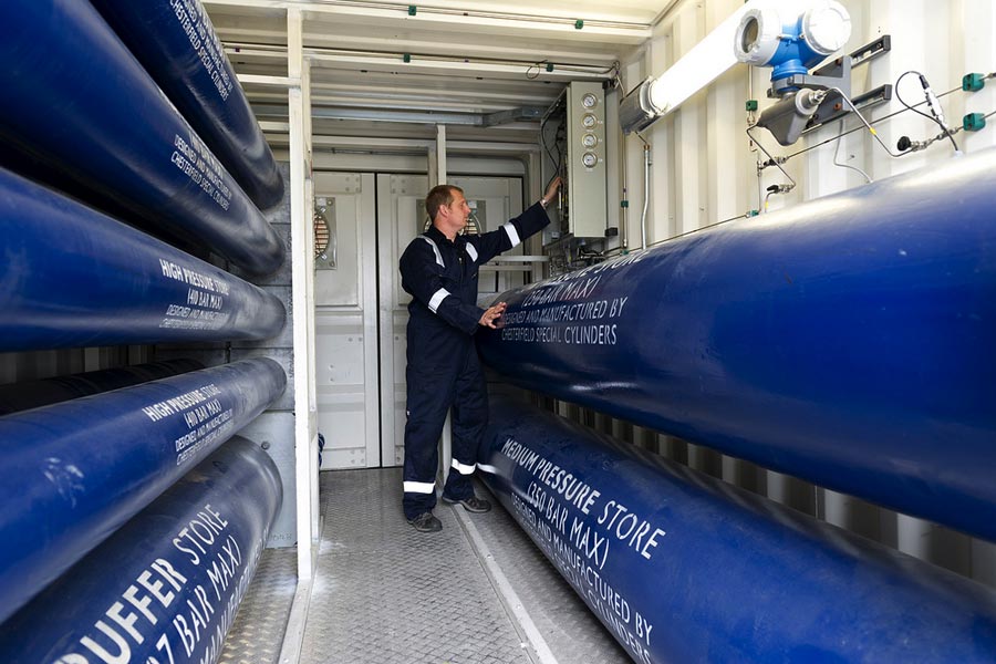
Spare electricity is used to split water into hydrogen and oxygen in a process called electrolysis, which can then be combusted to produce power when needed.
Super Capacitors
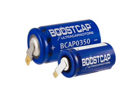
A super capacitor works much like a battery, but instead of using a chemical reaction to create a flow of electrons it simply temporarily stores them.
Compressed Air Energy Storage
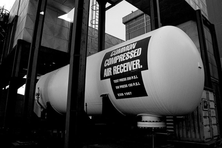
Spare Electricity within the grid is used to compress and store air under pressure, which can then be released on demand to make electricity.
Flywheel Energy Storage

A flywheel can be viewed as a mechanical battery because it converts electrical energy into kinetic energy, which can be converted back when needed.
Pumped Storage

Pumped storage involves pumping water up hill when there is excess electricity; this water can then be released at any moment to produce electricity.
Windstalker

The windstalker concept involves tall, grass like structures that use piezoelectric material to harness electricity through the wind's kinetic energy.
VIVACE

Harnessing vibrations from oceans, this technology is extracting energy from flowing water currents, which is different to conventional marine power.
Solar Updraft Towers
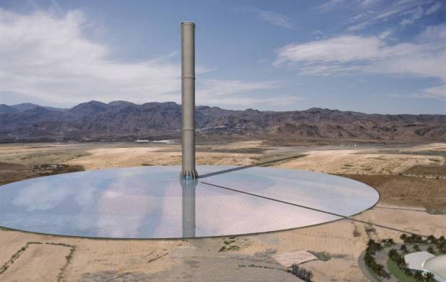
Solar updraft towers use solar energy to create strong updraft currents that can be harnessed to drive conventional turbines that produce electricity.
Solar Energy From Space

Technology that captures solar power in orbit where it is constant and stronger than on Earth. This then gets beamed & converted to electricity.
Piezoelectric Materials

Placing mechanical stress on a piezoelectric materials can create an electric current, so activities like dancing or running has the potential to power a city.